A neutron detector using integrated circuits
2 Department of Electrical and Computer Engineering, Texas A&M University, Texas, USA, Email: sunilkhatri@tamu.edu
Received: 18-Aug-2017 Accepted Date: Oct 25, 2017; Published: 05-Nov-2017
Citation: Shah MD, Marianno CM, Khatri SP, et al. A neutron detector using integrated circuits. J Mod Appl Phys. 2017;1(1): 03-07.
This open-access article is distributed under the terms of the Creative Commons Attribution Non-Commercial License (CC BY-NC) (http://creativecommons.org/licenses/by-nc/4.0/), which permits reuse, distribution and reproduction of the article, provided that the original work is properly cited and the reuse is restricted to noncommercial purposes. For commercial reuse, contact reprints@pulsus.com
Abstract
With the advancements and miniaturization in semiconductor technology, the circuits within integrated circuits have become increasingly sensitive to the effects of radiation, and therefore, are susceptible to improper functioning in high radiation fields. The researchers at Texas A&M University have been able to manipulate this disadvantage into an advantage for radiation detection applications, by designing the radiation integrated circuit (RIC). The RIC consists of two regions, radiation-sensitive areas (RSAs) and radiationhardened areas (RHAs). To employ RICs for neutron detection purposes, a neutron reactive material is required to generate charged particles, which interact with the RSAs. This report presents the research and investigation carried out on natural boron (19.9% 10B), enriched boron (96% 10B), boron carbide (~75% 10B), and lithium fluoride (~24% 6Li) as the neutron-reactive coating. To do this, MCNPX (Monte Carlo N-Particle eXtended) simulations were performed, to assess the neutron detection performance of these coatings on the RICs. The analysis focused on determining the optimal yield of charged particles at the RIC-coating interface. In addition, a signal to noise (S/N) ratio was investigated that analyzed energy deposition from heavy charged particles (HCPs) compared to electrons. The highest yield of charged particles was tallied for the enriched boron, followed by boron carbide, lithium fluoride, and natural boron. For the 3-μm thick enriched boron coating, the highest yield of charged particles was estimated entering the RIC to interact with the RSAs. With this optimal thickness of enriched boron, HCPs deposited three orders of magnitude more energy than electrons. This indicated the noise created from electrons interactions would be insignificant compared to the signal produced by the HCPs.
Keywords
Semiconductor; Isotope; Neutron; Radiation; Electron
Introduction
Radiation integrated circuit
Researchers at Texas A&M University have designed an integrated circuit (IC) for deployment as a new radiation detection medium [1]. Because most ICs are susceptible to radiation-induced failures, decades of research have gone into solving this problem. The research at Texas A&M University has led to a new type of IC that contains both radiation-sensitive areas (RSAs) and radiation-hardened areas (RHAs) [1,2]. These specially designed ICs can be used to detect radiation, and thus, they are referred to as radiation integrated circuits (RICs).
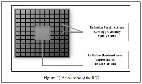
Figure (1) is a simple depiction of the RIC design. The RSAs contain electrical circuits that are sensitive to charged particles, which are arranged in an array. An RHA, designed to be highly resistant to radiation effects, is used to monitor RSAs for changes in their electrical properties in a round-robin manner. If an RHA registers “no change” in a particular RSA, that RSA is skipped, and the RHA observes the next RSA. The RHA detects the presence of radiation by sensing a “change” in the electrical behavior of an RSA. The “change” signifies a variation in the current and voltage parameters from the normal operating values.
The electrical properties of the RSA are a function of the type of radiation which has interacted in the RSA. If the RIC was used for gamma-ray detection system, the recovery time for the RSA will be approximately 230-ns, which is the decay time constant in the sodium iodide (NaI) crystal [3]. Whereas, for the neutron detection capabilities, the recovery time will be approximately 40-ns. This time represents the relaxation time for alpha-particles. Any RHA on the RIC can collect electrical signals from 40 RSAs in a manner that is electrically feasible, based on a worst-case internal clock rate of 1-GHz [1,2].
Upwards to a million (~106) RSAs can be fabricated on a 1-cmx1-cm RIC, composing about 75% of the chip area. This configuration allows for the remaining area to be comprised of tens of thousands (~104) of RHAs, equaling about 5% of the chip area (2). When fabricated, the remainder of the RIC would be used to implement signal processing and clock signal. The RIC design offers a high detection area (~75% of the chip area)-improving the geometric efficiency by offering a larger detection area than the comparable semiconductor-based neutron detectors, simplifying the electronics, requiring no additional peripheral devices, resulting in a relatively inexpensive, small, and low-power detector when produced in bulk [2,4-9].
Semiconductor neutron detector
Recently various efforts have been made to develop semiconductor-based neutron detectors that are like the RICs [4-9]. Primary factors for this development are device footprint and power requirement. Moreover, the shortage of Helium-3 (3He) for neutron detectors has encouraged the development of semiconductor-based detectors. Detectors of this type can be compact and less power-intensive than gaseous or scintillator-based systems. The semiconductor neutron detectors indicate a better sensitivity (intrinsic efficiency) to neutrons than the widely deployed 3He detectors [5,7-9]. RICs possess the same advantages such as reduced footprint of the detector and simplified power requirement.
To employ RICs for neutron detection, a neutron-reactive material is required to generate charged particles which can interact with the RSAs. Various methodologies permit for a neutron-reactive material to be present on the semiconductor. One method is coating the semiconductor with a material that has a high thermal neutron capture cross-section. For the purposes of developing the RIC, analysis was necessary for understanding the secondary charged-particle generation off the neutron-reactive coating, and how it would behave in the RSA. To assess the performance of neutron-reactive coatings and optimize the RIC-Neutron detector, simulations were performed using the Monte Carlo N-Particle eXtended (MCNPX) code [10,11]. Results obtained from these analyses will be used to optimize the RIC size for neutron detection.
Neutron-reactive materials
The MCNPX simulations were used to investigate widely employed neutronreactive materials; boron, boron carbide (B4C), and lithium fluoride (LiF) [12,13]. These materials are of interest, because they produce charged-particles that can interact with the RSAs following the absorption of a neutron. Thus, permitting the RICs to be used for neutron detection.
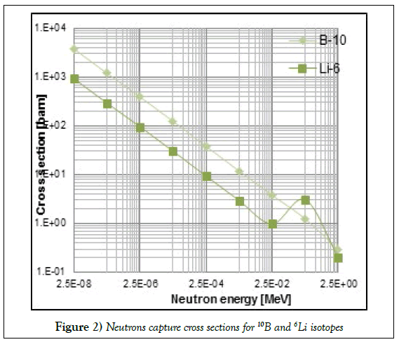
About natural boron, this is comprised of two isotopes, 10B (Boron-10) and 11B (Boron-11). The 10B isotope has a natural abundance of 19.9% and a high thermal neutron absorption cross-section (Figure 2) [14]. When neutron absorption occurs in 10B, heavy charged-particles (HCPs), namely lithium (7Li) and an alpha particle (α), are emitted instantaneously (time scale on the order of 10-18-sec) [13]. In addition to the HCPs, a gamma of 0.48-MeV is emitted 94% of the time [13]. The RIC can detect the resulting HCPs, but is insensitive to the resulting gamma ray. For the neutron-reactive material analysis of boron, simulations were performed using both natural boron and enriched boron (96% 10B).
For the B4C and LiF simulations, isotopic enrichment was considered. In B4C, boron content by weight is 78%. In order to increase the probability of HCP generation the boron was enriched to 96% 10B. Thus, in the simulations utilizing B4C, the 10B content was ~75%. The 6Li isotope in LiF absorbs a thermal neutron to produce two charged-particles (CPs) instantaneously, i.e., a triton (3H) and an alpha particle. Figure 2 presents the 6Li absorption cross-sections for thermal neutrons [14]. To enhance CP generation, 6Li content was enriched to 89% (by weight). In our simulations employing a LiF coating, the neutron-reactive 6Li isotope was ~24%.
Material and Methods
MCNPX Detector model
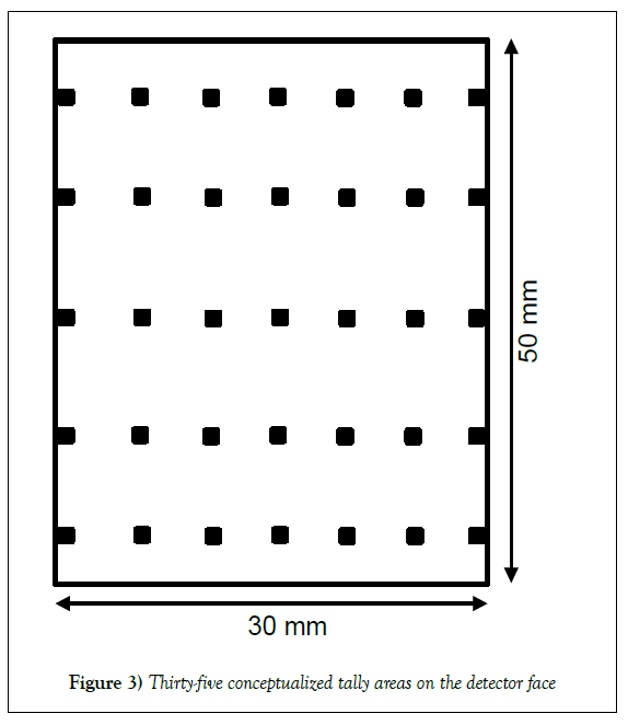
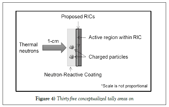
MCNPX simulations focused on measuring the number of charged-particles that reach the RIC after crossing the neutron-reactive coating. For each simulation, the coating layer had a surface area of 30-mmx50-mm and was placed on top of a 2.002-mm thick silicon layer to model the RIC. Of the total silicon covering, the 0.2-μm thick layer adjacent to the neutron-reactive coating serves as the RIC detection/sensitive region, while the rest of silicon represents the signal processing circuitry. The number of charged-particles crossing through the neutron-reactive layer and entering the silicon was tallied across 1-mm2 areas (represents the collective 40,000 RSAs).
The RIC-Neutron detector, leverages the neutron-reactive coating to generate secondary charged-particles (CP) that can interact in the RIC. It is important to understand that in addition to the HCP, which are generated following the neutron reaction, electrons are also produced as the HCPs lose energy in the reactive material. However, for performing the neutron detection, the RIC relies on HCPs as their impact on the RSA is significant. The HCPs generate a stronger signal than the electron by depositing majority of their energy in the RSA sensitive region (2-μm thick silicon). However, orders of magnitude more electrons are produced per HCP as they slow down. This difference in energy deposition occurs as the HCP has a maximum penetration depth (MPD) of the order of μm, about hundredth time lower than the electron’s MPD. Thus, in this research analysis, CP/HCP entering the silicon forms the signal component, while electrons entering the silicon is a noise.
MCNPX Scoring Regions
Each 1-mm2 scoring area was bounded by two lines in both the X and Y-planes. Two lines along the Y-plane were conceptualized at various positions such that there were five uniformly separated 1-mm intervals; as listed in Table 1. Two lines along the X-plane were theorized at various positions such that there were seven 1-mm intervals; as seen in Table 1. These intervals were separated uniformly except the first one (as the probe length was 30-mm). The intervals from Table 1 give a total of thirty-five 1-mm2 tally surfaces across which the yields of charged-particles were tallied (Figure 3). The tally regions distributed across the model detector were used to assess the trend of the charged particle yield. The yield or number of charged-particles obtained from MCNPX simulations represents the count of particles entering the silicon material per emitted mono-energetic neutron (n) [#n-1 mm-2].
| 1-mm Intervals | ||||
|---|---|---|---|---|
| X-axis [mm] | Y-axis [mm] | |||
| 0-1 | 14-15 | 29-30 | 4.5-5.5 | 34.5-35.5 |
| 4-5 | 19-20 | 14.5-15.5 | 44.5-45.5 | |
| 9-10 | 24-25 | 24.5-25.5 | ||
Table 1: The intervals over x and Y-axes to form the tally areas
MCNPX Simulations
Two sets of simulations were performed for each coating. In the firsset of simulations, the coating thickness was varied, while using a monoenergetic neutron point source of 0.025-eV. This source was centered and placed 1-cm away from the detector face (Figure 4). Source-to-detector distance was unimportant because these simulations were only employed to determine the optimal thickness at which the highest number of heavy ions enter the RICs. For determining the optimal thickness, the coating thickness was varied over a wide range from 0.5-μm to 100-μm.
The second set of simulations was performed in which the neutron energy was varied by a factor of ten from 0.025-eV to 2.5-MeV. In these simulations, the coating layer was the optimal thickness that was determined earlier with the source placed 1-cm away from the center of the detector face. This analysis provided an understanding of the yield of charged-particles as a function of neutron source energy. These two sets of simulations were performed on each neutron-reactive material to analyze them comprehensively, conclude the optimal detector design, and optimize the RIC size.
Thermal neutron sensitivity
The thermal neutron sensitivity analysis was performed for the optimal thickness of each coating material. The sensitivity is defined as the ratio of number of charge carriers generated in the sensitive region of the detector to the neutron flux density observed in the neutron-reactive material [15]. The number of charge carriers created in the silicon, the sensitive region of the detector, depends on the energy deposited (E) by the electrons and HCPs (Equation 1). This deposited energy for each particle was estimated using the F6 tally in MCNPX [11]. The charge carrier relation is given as, E (eV) * 3.6-1, where 3.6 is the energy (eV) required to generate one charge carrier in silicon, also known as ionization threshold energy [13]. This analysis was performed to compare the sensitivity of the RIC neutron detector to a 3He detector, with a 2.54-cm diameter and effective length of 30.48-cm. This tube held at 20-atm has the thermal neutron sensitivity of 73 cps-nv-1 (counted pulses per neutron flux density) [16].
 (1)
(1)
Signal to noise ratio
In the coating material, the HCPs generate electrons through ionization that interact with the RSAs to generate an electric signal. In addition, when the boron absorbs a neutron, a gamma-ray is emitted 94% of the time that also liberates electrons through ionization in the coating material or silicon (RIC). These electrons will create a “noise” component that potentially could interfere with the signal produced by the HCPs. An analysis was carried out to assess the signal to noise (S/N) ratio, while employing an optimal thickness in the detector. Using the MCNPX tally, energy deposited by HCPs and electrons in the 0.2-μm silicon while crossing the center 1-mm2 tally area were estimated. This estimation was employed to gauge their individual contribution. For the analyses, a term was defined as the Energy S/N, which is the amount of energy deposited within the silicon by entering HCPs to the energy deposited by entering electrons. With the ionization energy in silicon being constant, this fraction will be consistent with the expectation.
Results and Discussion
Boron
Using MCNPX, an analysis was performed on both natural boron and enriched boron to compute the number of HCPs crossing the coating layer to interact in the RSAs. Table 2 highlights the simulation results for both natural boron and enriched boron. From each simulation (for a thickness layer), only the highest number of HCPs tallied across the thirty-five 1-mm2 areas is presented. For the coating thickness varied from 0.5-μm to 100-μm, the results presented in Table 2 yielded the highest sum of HCPs. The values listed are counts across 1-mm2 area per emitted mono-energetic neutron. The relative errors associated with these results are less than 6%. Additionally, the contribution from alpha-particles and lithium ions are also listed for each analysis in Table 2. The highest count for all these simulations was tallied across the same 1-mm2 area that was directly in front of the source (X-axis interval [mm]: 14-15; Y-axis interval [mm]: 24.5-25.5). The other 1-mm2 areas had lower yield, and the magnitude continually decreased for areas that were further away from the source.
| Thickness [µm] | Natural boron yield (19.9% 10B) |
Enriched boron yield (96% 10B) |
||||
|---|---|---|---|---|---|---|
| Α | 7Li | Sum | α | 7Li | Sum | |
| 1 | 3.64 x 10⁻⁶ | 2.91 x 10⁻⁶ | 6.55 x 10⁻⁶ | 1.68 x 10⁻⁵ | 1.31 x 10⁻⁵ | 2.98 x 10⁻⁵ |
| 2 | 6.25 x 10⁻⁶ | 3.48 x 10⁻⁶ | 9.73 x 10⁻⁶ | 2.75 x 10⁻⁵ | 1.36 x 10⁻⁵ | 4.11 x 10⁻⁵ |
| 2.5 | 7.04 x 10⁻⁶ | 3.31x10⁻⁶ | 1.03x10⁻⁵ | 3.02 x 10⁻⁵ | 1.32 x 10⁻⁵ | 4.33 x 10⁻⁵ |
| 3 | 7.69 x 10⁻⁶ | 3.31 x 10⁻⁶ | 1.1 x 10⁻⁵ | 3.28 x 10⁻⁵ | 1.32 x 10⁻⁵ | 4.6 x 10⁻⁵ |
| 4 | 8.35 x 10⁻⁶ | 3.26 x 10⁻⁶ | 1.16 x 10⁻⁵ | 3.19 x 10⁻⁵ | 1.22 x 10⁻⁵ | 4.4 x 10⁻⁵ |
| 5 | 8.13 x 10⁻⁶ | 3.28 x 10⁻⁶ | 1.14 x 10⁻⁵ | 3.01 x 10⁻⁵ | 1.15 x 10⁻⁵ | 4.15 x 10⁻⁵ |
Table 2: The number of HCPs per mono-energetic neutron that reach the RIC as a function of coating thickness for the natural and enriched boron detectors
The results in Table 2 show that the highest yield of HCPs is for the 4-μm thick natural boron and 3-μm thick enriched boron. The difference in the optimal thickness is attributed to the difference in neutron-reactive content, because natural boron has a 19.9% abundance of 10B and enriched boron has a 96% abundance of 10B. The HCP yield is larger for enriched boron by at least a factor of 3.6X as it has the neutron-reactive content (10B) higher than natural boron by a factor of 4.8X. For both natural boron and enriched boron detectors, it was observed that the contribution of alpha-particles was greater than lithium-particles by at least a factor of 1.25X due to the larger MPD for alpha-particles than lithium ions in boron [13]. The amount of energy deposited in the silicon was greater for alpha-particles by a factor of 2.09X and 2.10X for the 4-μm thick natural boron and 3-μm thick enriched boron, respectively.
For the 3-μm thick enriched boron, thermal neutron sensitivity and Energy S/N analyses were carried out. The thermal neutron sensitivity of the RIC was estimated to be 17-cps-nv-1 with the relative error under 5%, which is lower by a factor of 0.23X than the sensitivity of the reference 3He tube. The Energy S/N is estimated at 3633X, which implies HCPs, namely alpha and 7Li-particles, deposit energy up to three orders of magnitude times higher than electrons in silicon. Overall, for the boron coating, the major contributor to the electric signal generation in the RICs is alpha-particle.
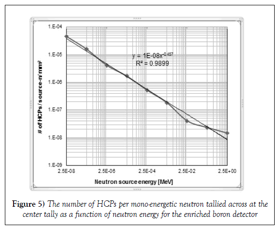
Based on the yield of charged particles, the next set of simulations was performed with enriched boron as the coating material. The dimensions of this coating were modified to 30-mm x 50-mm x 3-μm with a 0.2-μm thick silicon layer in contact with it. This set of simulations was performed with the mono-energetic neutron source placed 1-cm away, while varying the neutron energy by a factor of ten from 0.025-eV to 2.5-MeV. Figure 5 illustrates the highest yield of HCPs obtained across the center tally area as a function of the neutron energy. In addition, the corresponding uncertainty (1-σ) for each result is shown in the plot. The yield across each 1-mm2 tally is per emitted mono-energetic neutron. Each of these results has a relative error of less than 3%. It was observed the best-fit trend-line was a power function with an exponent value of -0.457 and had an R2 value of 0.9899. The power function is a distinctive feature which can be expected as the 10B neutron capture cross section that is proportional to the neutron energy (E) as E-0.5. It can be observed that the yield for the 25-keV and 2.5-MeV neutron does not fit on the trend line and thus, the difference in the expected and observed trend (Figure 5). The neutron capture cross section for 10B has a small resonance for the 2.5-MeV neutron [14]. This resonance has caused the slight increase in the yield for the 2.5-MeV neutron; as seen in Figure 5.
Boron carbide
MCNPX simulations were performed to determine the optimal thickness for boron carbide that yields the maximum number of HCPs for interactions in the RIC. Table 3 provides results for the highest measurement in a set of thirty-five 1-mm2 areas as a function of thickness. The reported results are per emitted mono-energetic neutron and have relative errors less than 5%. Similar to enriched boron, boron carbide has an optimal thickness at 3-μm from the wide range (0.5-μm to 100-μm) modeled. However, the yield for B4C was lower by 0.8X compared to enriched boron due to the lower number of 10B atoms in B4C.
| Thickness [µm] | Boron carbide yield (~75% 10B) |
||
|---|---|---|---|
| α | 7Li | Sum | |
| 1 | 1.38 x 10⁻⁵ | 1.05 x 10⁻⁵ | 2.43 x 10⁻⁵ |
| 2 | 2.24 x 10⁻⁵ | 1.09 x 10⁻⁵ | 3.33 x 10⁻⁵ |
| 2.5 | 2.47 x 10⁻⁵ | 1.08 x 10⁻⁵ | 3.55 x 10⁻⁵ |
| 3 | 2.64 x 10⁻⁵ | 1.05 x 10⁻⁵ | 3.69 x 10⁻⁵ |
| 4 | 2.61 x 10⁻⁵ | 1.03 x 10⁻⁵ | 3.63 x 10⁻⁵ |
| 5 | 2.44 x 10⁻⁵ | 9.21 x 10⁻⁶ | 3.36 x 10⁻⁵ |
Table 3: The number of HCPs per mono-energetic neutron reaching the RIC as a function of coating thickness for the B4C detector
Equivalent to boron and enriched boron analysis, individual CP contributions were analyzed for B4C coating to assess the Energy S/N capability. The 3-μm thick B4C coating shows a significant contribution from alpha particles, which was larger than lithium ions by 2.51X. It was also observed that the energy deposited in the silicon was 2.09X larger for alpha particles. The Energy S/N was estimated at 3372X, which indicates the amount of energy deposited in silicon by HCPs, alpha and 7Li-particles, was three orders of magnitude larger than electrons. Overall, in the B4C, the primary dependence is on alpha-particles to generate an electrical signal in the RICs.
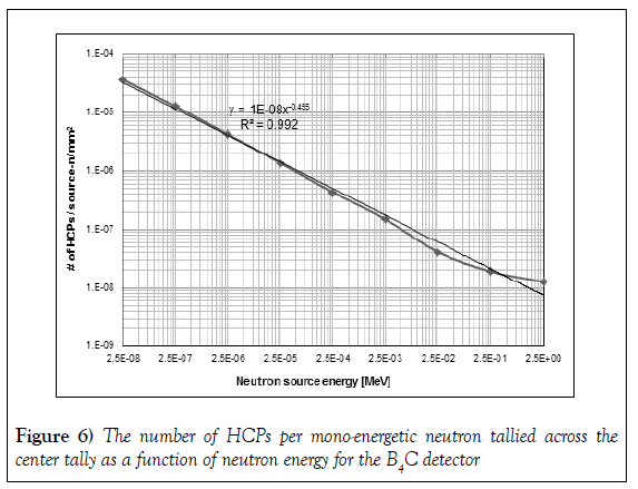
Based on the yield of HCPs, the next set of simulations were carried out with the B4C coating dimension as 30-mm x 50-mm x 3-μm. For this set of simulations, the highest yield of HCPs tallied was across the center tally. Figure 6 presents the tally of HCPs per mono-energetic neutron source for nine different source energies. The source energy was varied by a factor of ten from 0.025-eV to 2.5-MeV. The relative errors associated with these results are less than 3.8%. The 1-σ error bars are not visible on the plot because the data point is obscuring them. In these simulations, the source was placed 1-cm away from the detector face, which encloses a 3-μm thick B4C coating on top of a 2.002-mm thick piece of silicon. A power function was found to be the best-fit having an exponent value of -0.455 and R2 value as 0.992. This function, which follows 10B neutron capture cross section profile was expected as observed in the enriched boron analysis.
Lithium fluoride
The first set of simulations with a lithium fluoride coating indicates a lower yield of HCPs, triton and alpha-particles, compared to both the enriched boron and boron carbide analysis (Table 4). This difference is attributed to the concentration of the neutron-reactive element and its absorption cross section, which are lower for lithium fluoride. The neutron-reactive content by weight was 96% 10B in enriched boron, ~75% 10B in boron carbide, and ~24% 6Li in lithium fluoride.
| Thickness [µm] | Lithium fluoride yield (~24% 6Li) |
||
|---|---|---|---|
| 3H | α | Sum | |
| 10 | 1.71 x 10⁻⁵ | 4.62 x 10⁻⁷ | 1.76 x 10⁻⁵ |
| 20 | 2.56 x 10⁻⁵ | 4.17 x 10⁻⁷ | 2.6 x 10⁻⁵ |
| 25 | 2.70 x 10⁻⁵ | 4.08 x 10⁻⁷ | 2.74 x 10⁻⁵ |
| 30 | 2.66 x 10⁻⁵ | 3.75 x 10⁻⁷ | 2.7 x 10⁻⁵ |
| 40 | 2.49 x 10⁻⁵ | 3.48 x 10⁻⁷ | 2.53 x 10⁻⁵ |
| 50 | 2.31 x 10⁻⁵ | 3.08 x 10⁻⁷ | 2.34 x 10⁻⁵ |
Table 4: The number of HCPs per mon-energetic neutron reaching the RIC as a function of coating thickness for the LiF detector
Each result in Table 4 is the yield of HCPs measured across 1-mm2 area per emitted mono-energetic neutron and have relative error less than 7%. The highest yield of CPs was attained using 25-μm thick lithium fluoride from the wide range 0.5-μm to 100-μm simulated. It was noticed that 3H-particles had a higher contribution to the tally by a minimum factor of 37X alpha particles. Additionally, the amount of energy deposited by 3H-particles was greater by a factor of 17X for the 25-μm thick LiF. This difference in contribution is explained by the MPD of alpha-particles, which was lower than 3H-particles in the LiF [13]. Since the MPD of 3H-particles is large compared to alpha-particles in silicon, there is a lower probability of interaction within 0.2-μm thick silicon. The lower probability means the number of charged-particles crossing through the silicon without depositing their energy will be larger for 3H-particles. This fraction was observed as 3.5% and 21.6% for 3H and alpha-particles, respectively, for the 25-μm thick LiF.
In the Energy S/N analysis for the 25-μm thick LiF, the complete energy deposition within the 0.2-μm thick silicon occurs more for alpha-particles by a factor of 6.17X than 3H particles. These events of complete energy deposition within the silicon, representing the RIC sensitive region, serve to detect the presence of neutrons. The Energy S/N was estimated as 1354X. While this ratio indicates higher energy, deposition occurs by CPs in LiF simulations, this Energy S/N ratio was lower than the enriched boron case (by 0.37X) and the B4C case (by 0.40X). However, these results imply that for all three-coating materials alpha-particles are the dominant source of electric signal generation in the RICs.
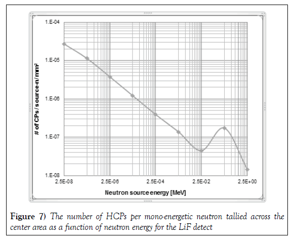
In the second set of LiF simulations, the 25-μm thick LiF was modeled to assess the yield as a function of emitted neutron energy. Figure 7 presents the highest yield across thirty-five tally areas relative to the mono-energetic neutron source. The plot is on a log-log scale to show the trend in yield. The results have relative errors less than 6%. It is evident the highest yield was at 0.025-eV but was lower than the highest yield for enriched boron at 0.025-eV by a factor 0.6X. The difference in yield is a property of the cross-section and neutron-reactive content.
The trend in yield as a function of emitted neutron energy was as expected (Figure 2). From thermal energy to a few hundred eV, the yield was proportional to neutron energy as E-0.5. Above this energy, the 6Li cross section first rises and then falls. This phenomenon widely known as resonance was also observed in the yield of HCPs. For the 250-keV neutron, the yield of HCPs was larger than the 25-keV neutron and 2.5-MeV neutron. In other words, for the 250-keV neutron, a resonance was observed in the yield of charged particles, which is similar to the resonance in cross section of 6Li (Figures 2 and 7).
Conclusion
Natural and enriched boron, boron carbide, and lithium fluoride are popular neutron-reactive materials for semiconductor-based neutron detectors. These materials were investigated by using the MCNPX code to gain design information for the RIC-neutron detector. The neutron-reactive content in these materials were simulated at 19.9% 10B, 96% 10B, ~75% 10B, and ~24% 6Li, respectively. It was observed that the highest yield of charged-particles was tallied for the enriched boron, followed by boron carbide, lithium fluoride, and natural boron. In other words, the content of the neutronreactive material regulates the yield of charged particles.
The enriched boron and boron carbide have an optimal thickness of 3-μm, at which lengths these materials yield the highest number of charged particles. The lithium fluoride and natural boron have an optimal thickness of 25- μm and 4-μm, respectively. Each of these coatings had a surface area of 30- mm x 50-mm. For each coating material, the yield of charged-particles was tallied highest across the same center tally area that was directly in front of the source. Other 1-mm2 areas had lower yields, and the yield magnitudes decreased for areas that were further away from the source, placed at the center.
Consistently, a decrease in the yield of charged-particles was observed when the neutron energy was increased. The yield was observed to be proportional to neutron energy as E-0.5 from thermal energy up to a few hundred keV for LiF and up to a few MeV for enriched boron and B4C. The trends in the yield of charged-particles are like the trends of their corresponding cross sections (function of the neutron energy).
Another important observation was the individual contribution made by the different charged-particles to the total yield. The 7Li-particles, being heavy, were not able to contribute much to the yield compared to alpha-particles in enriched boron and boron carbide systems. Although 3H-particles contributed significantly to the yield in LiF simulations, the number of events in which they completely deposited their energy was lower by a factor of 0.16X than the alpha-particles. This is important because each event of complete energy deposition within the silicon (RIC sensitive region) facilitates neutron detection. With respect to facilitating neutron detection, alpha-particles contribute most significantly, because they dominate the signal generation in the RICs for all coating materials.
The Energy S/N for the thermal neutron source was 3633X for the enriched boron system. This ratio for enriched boron was higher than B4C and LiF by 1.08X and 2.7X, respectively. This Energy S/N analysis helped to evaluate the RICs capability to detect neutrons and propose the neutron detector design. The RIC-neutron detector will use enriched boron (96% 10B) as the neutron-reactive material having a coating thickness of 3-μm. The thermal neutron sensitivity of the RIC was estimated to be 17-cps-nv-1 (counted pulses per neutron flux density) with relative error under 5%, which can be increased by stacking the RICs. This sensitivity is comparable to the sensitivity of the 3He tube, and so the RIC neutron detector, when perfected, can be an alternative to the 3He detectors.
Acknowledgement
Authors would like to thank Dr. Sunil Chirayath, a research assistant professor in the Department of Nuclear Engineering at Texas A&M University for his valuable guidance.
REFERENCES
- Jayakumar GN, Khatri S. A Design Approach for Radiation-hard Digital Electronics. ACM/IEEE Design Automation Conference (DAC). 2006:773-8.
- Garg R. Analysis and Design of Resilient VLSI Circuits, Dissertation, Texas A&M University. 2009.
- Shah M. Radiation Detection Using Integrated Circuits, Dissertation, Texas A&M University. 2016.
- Montag B, Reichenberger M, Arpin K, et al. Synthesis and Characterization of LiZnP and LiZnAs Semiconductor Material, J Crystal Growth. 2015;412:103-8.
- McGregor D, Shultis K. Spectral Identification of Thin-Film-Coated and Solid-Form Semiconductor Neutron Detectors, Nuclear Instruments and Methods in Physics Research A. 2004;517:180-8.
- Barbagallo M, Cosentino L, Forcina V, et al. Thermal Neutron Detection Using a Silicon Pad Detector and 6LiF Removable Converters. Review of Scientific Instruments. 2013;84: 033503.
- McGregor D, Shultis K. Reporting Detection Efficiency for Semiconductor Neutron Detectors: A Need for Standard, Nuclear Instruments and Methods in Physics Research A. 2011;632:167-74.
- Kouzes R, Ely J, Erikson L, et al. Neutron Detection Alternatives to 3He for National Security Applications, Nuclear Instruments and Methods in Physics Research Section A. 2010;623:1035-45.
- McGregor D, Bellinger S, Shultis K. Present Status of Microstructured Semiconductor Neutron Detectors, Journal of Crystal Growth. 2013;379:99-110.
- Pelowitz D, Durkee J, Elson J, et al. MCNPX 2.7.E Extensions, Los Alamos National Laboratory report LA-UR-11-01502. 2011.
- Pelowitz D. MCNPX User's Manual, Version 2.7.0, Los Alamos National Laboratory report LA-CP-11-00438. 2011.
- Knoll G. Radiation Detection and Measurement, John Wiley & Sons, New York Fourth Edition.
- Turner J. Atoms, Radiation and Radiation Protection, Wiley-VCH Verlag GmbH & Co. 2007.
- Chadwick M. ENDF/B-VII.0: Next Generation Evaluated Nuclear Data Library for Nuclear Science and Technology, Nuclear Data Sheets. 2006;107:2931.
- http://web.mit.edu/8.13/www/JLExperiments/38/tgm-neutron- detectors.pdf.
- http://www.lndinc.com/products/pdf/544/.


